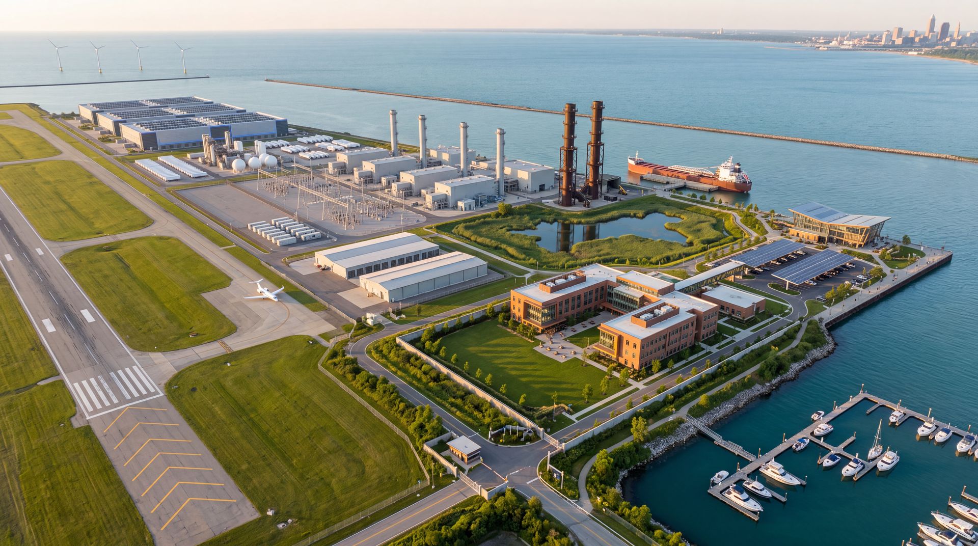
Concept rendering: golden-hour aerial of the Burke lakefront energy campus from the southeast, with the marina, the public campus and the downtown Cleveland skyline
Burke Lakefront · Cleveland, Ohio · Concept program

Burke Energy Campus

Lake Erie water, Cleveland’s own waste and clean firm power — turned into green hydrogen, green ammonia, hyperscale compute and a public shoreline, on the lakefront fill at Burke.

Proposed — illustrative only. Not an existing facility. No site control.
2GWNet generation at full build-outFull-peninsula scenario
12Integrated campus zones, one process loopRev E detail plans
~2.4miOf lakefront opened to the publicFull-peninsula scenario
1,200+Permanent jobs at full operationNE-peninsula scenario
0Acres of active airfield used in the airport-open planNE-peninsula scenario
01 · The system

One campus, one closed loop.

Every zone feeds another. The lake supplies water for hydrogen and cooling, city waste becomes feedstock instead of landfill, turbine exhaust becomes district heat, and the power island carries the compute. Nothing leaves the site that it could use.

How the campus worksLake water, offshore wind, natural gas and city waste are converted into green hydrogen, green ammonia, firm power and steam, which serve marine fuel, industry, hyperscale compute, the grid and the public campus.01 · INPUTS02 · CONVERSION03 · PRODUCTS04 · USESH₂ co-fireLake Erie waterdeep-water intakeOffshore windIcebreaker cableNatural gas → H₂blend rises over timeCleveland wastemunicipal solid wasteWater treatmentsoftening · RO · DIPEM electrolysiswater → H₂ + O₂7HA.03 power islandcombined cycle + HRSGFastOx gasificationwaste → syngas + slagGreen hydrogenstored at 350 barGreen ammoniaHaber-Bosch loopFirm powerislanding-capableSteam & heatdistrict heatingMarine fuel & exportbunkering pierFertilizer & industryNE Ohio corridorHyperscale computelake-cooled hallsGrid + public campusCPP · FirstEnergyLAKE LOOPDeep-water intake → heat exchangers → compute cooling → reoxygenation cascade → returned to Lake Erie

Swipe the diagram sideways to see all four columns →

Water & hydrogenPower & heatWaste to feedstockHydrogen co-fire back into the turbines
Power

GE Vernova 7HA.03 combined cycle

Heat-recovery steam on every unit, hydrogen co-fire capable, with a reserved parcel for a small modular reactor.

Resilience

Island-capable backup

Mainspring linear generators and Hyliion KARNO units plus battery storage, sized N+1 and fuel-flexible.

Molecules

Green hydrogen & ammonia

PEM electrolysis and Haber-Bosch synthesis for fertilizer, marine fuel and industrial export.

Compute

Lake-cooled hyperscale

Deep-water heat exchange for sub-1.1 PUE, with process water returned to the lake reoxygenated.

02 · The concepts

Three scales of the same idea.

The work has been developed as three linked concepts — from a campus that leaves the airport flying, to the full peninsula, to a schematic design drawn at true scale against FAA airspace. Each stands on its own and each has its own document set.

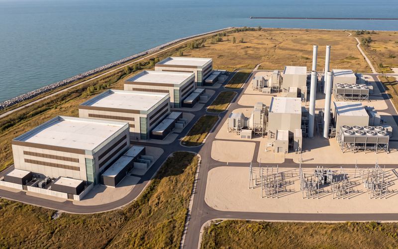
Concept aerial of the Burke lakefrontAirport stays open
Concept A · Rev D

NE Peninsula Energy Campus

Built only on the closed dredge-disposal peninsula at Burke’s northeast corner. The runway keeps flying, a secured gateway on the southeast side is the only way in, and a wall and vegetated buffer separate campus from airfield.

±150 acNE fill peninsula
500 MWData center, 1 GW-ready
180 t/dGreen hydrogen
2035Full operations
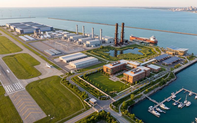
Golden-hour aerial of the full campusFull peninsula
Concept B · Rev E

Full-Peninsula Campus — 2 GW

The same system at full scale: five to seven combined-cycle blocks, a data center phased to 2 GW, a marine bunkering pier on the north bulkhead and roughly 2.4 miles of public lakefront.

~770 acFull peninsula footprint
2 GWNet output & IT load
12Zones, phased 2029–35
~$26BEst. fully loaded, incl. tenant data center
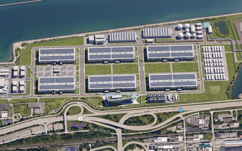
Concept aerial of four data halls and the energy blockDrawn to true scale
Concept C · FOS216-BEDC

Burke Energy & Data Campus

A schematic design of the 178-acre lakefront fill parcel, tested in two cases — airport operating and airport closed — against the FAA Part 77 surfaces that decide what can rise where.

178 acTraced lakefront parcel
1,000 MWIT load, 4 halls (airport closed)
1,272 MWTwo 7HA.03 blocks
0 galWater for air-cooled generation

How the three relate. Concepts A and B share one twelve-zone program at two footprints. Concept C starts from the ground up — a traced boundary, the runway geometry and the airspace — and is where the arrival gateway and the eye-level studies were developed. Figures belong to the concept they are listed under.

03 · The twelve zones

Where everything goes.

The full-peninsula plan divides the campus into twelve zones, each sized and phased on its own. Bars show footprint relative to the largest zone, the 180-acre data center.

01

Lake Erie Water Intake & Treatment

Submerged crib below the thermocline, fish-safe screens, RO + DI polishing, reoxygenated return.

Phase 1 · 2029–3140 ac
02

PEM Electrolyzer Farm

~750 MW of electrolysis, about 270 t of green hydrogen a day; oxygen sold as a byproduct.

Phase 1 · 2029–31130 ac
03

FastOx Gasification

Cleveland municipal waste to clean syngas and inert slag — zero landfill.

Phase 2 · 2030–3240 ac
04

GE Vernova 7HA.03 Power Island

5–7 combined-cycle blocks, ~2 GW net, HRSG steam for district heat, hydrogen co-fire capable.

Phase 1 · 2029–33150 ac
05

Haber-Bosch Green Ammonia

~2,200 t/day for fertilizer, marine fuel, and industrial export.

Phase 2 · 2030–3238 ac
06

Grid Interconnection & Substation

345 kV tie to Cleveland Public Power and FirstEnergy; islanding-capable.

Phase 1 · 2029–3116 ac
07

Offshore Wind Tie-In

Landing for the Icebreaker Wind cable; curtailed wind becomes stored hydrogen.

Phase 2 · 2030–328 ac
08

Marine H₂ / NH₃ Bunkering Pier

First Great Lakes port offering green marine fuel at scale.

Phase 4 · 2033–3420 ac
09

H₂ & NH₃ Storage Field

72-hour buffer that works as a grid-scale battery.

Phase 2 · 2030–3234 ac
10

Hyperscale Data Center

Phased 500 → 1,200 → 2,000 MW IT load, Lake Erie deep-water cooling, sub-1.1 PUE.

Phases 1–3 · 2030–35180 ac
11

Public Lakefront Campus

Promenade and Energy Discovery Center — about 2.4 miles of lakefront opened.

Phase 3 · 2031–3470 ac
12

Research & Education Campus

A live testbed for university and hospital research, and a K–PhD talent pipeline.

Phase 3 · 2031–3440 ac
Total zoned footprint 766 ac · Full peninsula ~770 acOpen the zone-by-zone plans →
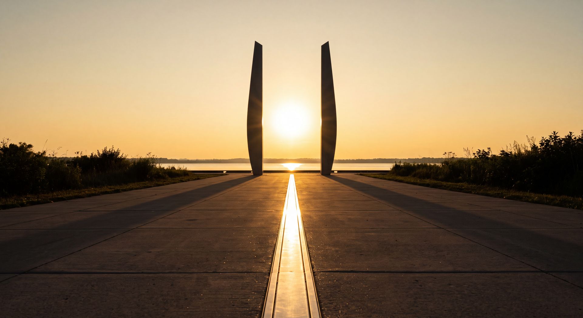
Concept rendering: the sun setting between two tall blades at the end of an inlaid stainless line on the greenway
The solstice sightline — the campus axis within about a degree of the June sunrise and December sunset
04 · The arrival
Axis 057.81°

The campus sits beside a working runway, where the law says almost nothing may rise. So the entrance is shaped by the airspace instead of fighting it — a piece of public art that is also an FAA compliance diagram.

  1. IThe Gradient

    Eighteen pairs of anodized blades off North Marginal Road, each shorter than the last, tracing the approach surface they stand in and touching the ground exactly where it ends.

  2. IIThe Traverse

    A short, level run along the campus axis to the head of the cut.

  3. IIIThe Cut

    A 1,200-ft open processional below grade, lined by a 720-ft kinetic fin wall — 7,200 bronze blades whose rows show the campus’s live compute load. It emits no light by day.

  4. +The Line

    A 42-ft blade pair and a 1,000-ft inlaid stainless strip on the public greenway — the tallest legal object on that half of the site, given to the public rather than the front gate.

05 · Design principles

Built around the airport, the lake and the public.

The rules that shaped the drawings, and that any version of this campus would have to keep.

The airspace sets the heights

Every mass is checked against the FAA Part 77 surfaces around runway 6L/24R. Where nothing may rise, the design goes down or steps back.

The shoreline stays public

The security line runs inboard of the fire lanes, so the lakefront greenway sits outside the fence and open to everyone.

Sky between the buildings

Four discrete halls on a 550-ft pitch rather than one continuous wall, leaving 320 ft of open sky between masses from the greenway.

Safe to fly over

Amber 2200K light only with zero uplight, no open water to draw birds, and no horizontal spans for them to perch on near the approach.

The lake gets its water back

Fish-safe intake screens, a closed cooling loop through heat exchangers, and a reoxygenation cascade before anything returns to Lake Erie.

A campus people can visit

An Energy Discovery Center, a research and education cluster, and a talent pipeline from Cleveland classrooms to the plant floor.

07 · Documents

The full record.

Proposals, detail plans, drawing sets and eye-level studies. Each opens as its own page.